Design Flow
Concept
- Consolidate the idea and generate draft specifications technical and financial for further evaluation
- Ascertain technical feasibility and generate most promising architectures
- Establish market feasibility, confirming customer need is satisfied and market share is suitable
- Check financials to ascertain that return on investment is attractive
- Refine the design functionality with a system simulation using performance values of available parts
- Re-evaluate market and financials with new formulated design
- Fully simulate the design concept and quantify performance issues (Spectral mask, Isolation and EMC)
- Document the design concept and confirm any specification changes are acceptable for all stakeholders
Product development
- Build a comprehensive product breadboard to demonstrate concept functionality
- Design review the breadboard results for the required specifications
- Reiterate circuit design, simulation and definition based on design review findings
- Design manufacturing and test process
- Update documentation and confirm any changes with all stakeholders
- PCB Design and layout to fit agreed form factor
- Build design prototypes
- Build a representative manufacturing test system
- Test the prototypes and check manufacturing test system concurs
Volume production
- Advertise the upcoming release
- Consolidate any DFM issues found in the prototypes into the pilot layout and build
- Use pilot build to demonstrate manufacturability including documentation
- Pilot units to be used for final regulatory testing and customer demonstrations
- Update / refine documentation and confirm any changes with all stakeholders
- Start first production phase and confirm volume, rates and cost goals
Product sustaining and obsolescence
- Review the manufacturing test results
- Streamline and refine manufacturing process
- Consolidate any DFM issues found in pilot manufacture
- Update manuals and documentation accordingly
- Research available alternative components or consider a sub circuit add-on when components become obsolete
Prototyping ancillaries
PCB assembly and rework equipment
- Microscope
- Soldering rework station
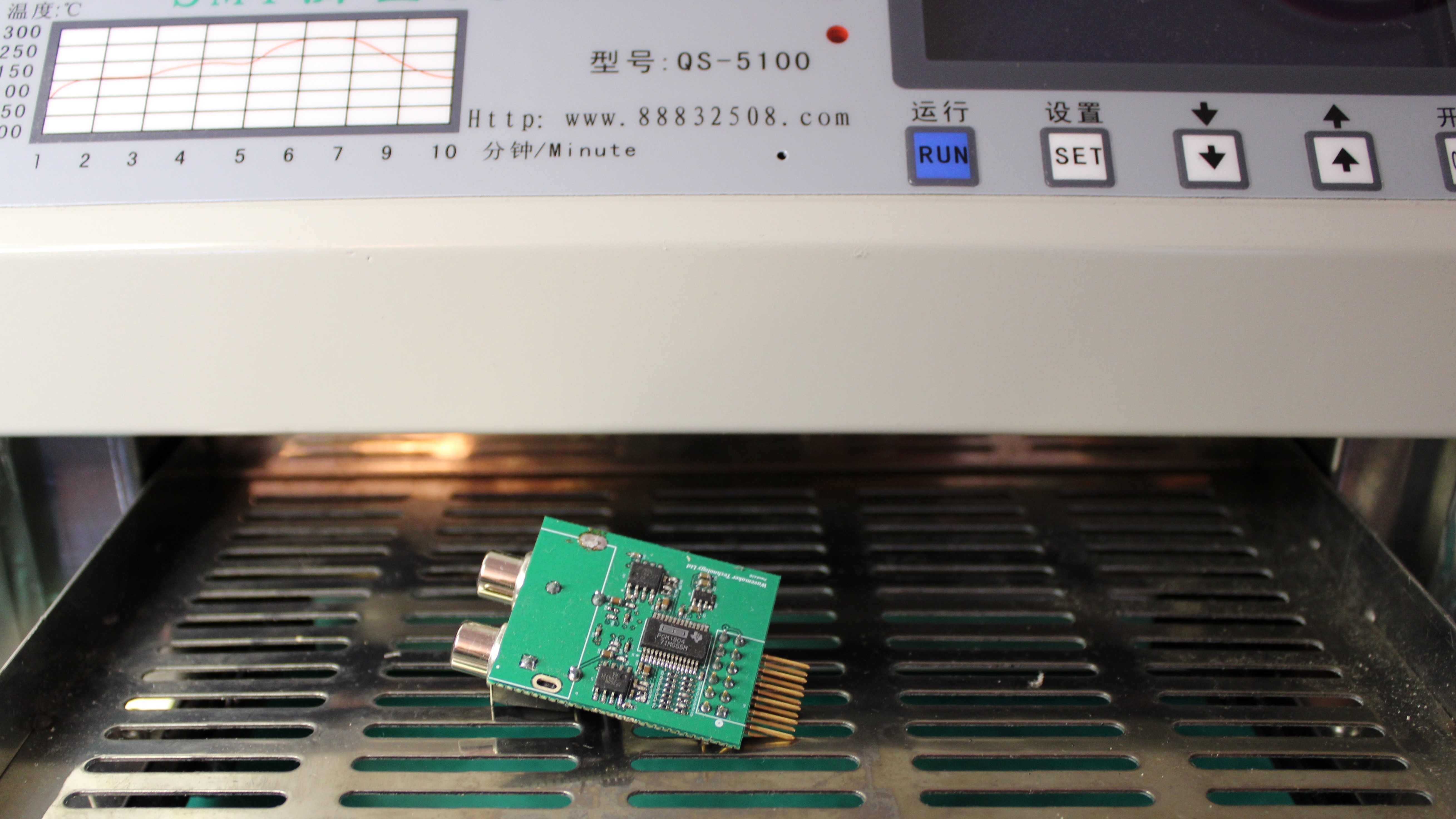
- Reflow oven
Lab test equipment
- Oscilloscope
- Spectrum analyser
- Signal generator
- Power supply
Design tools available
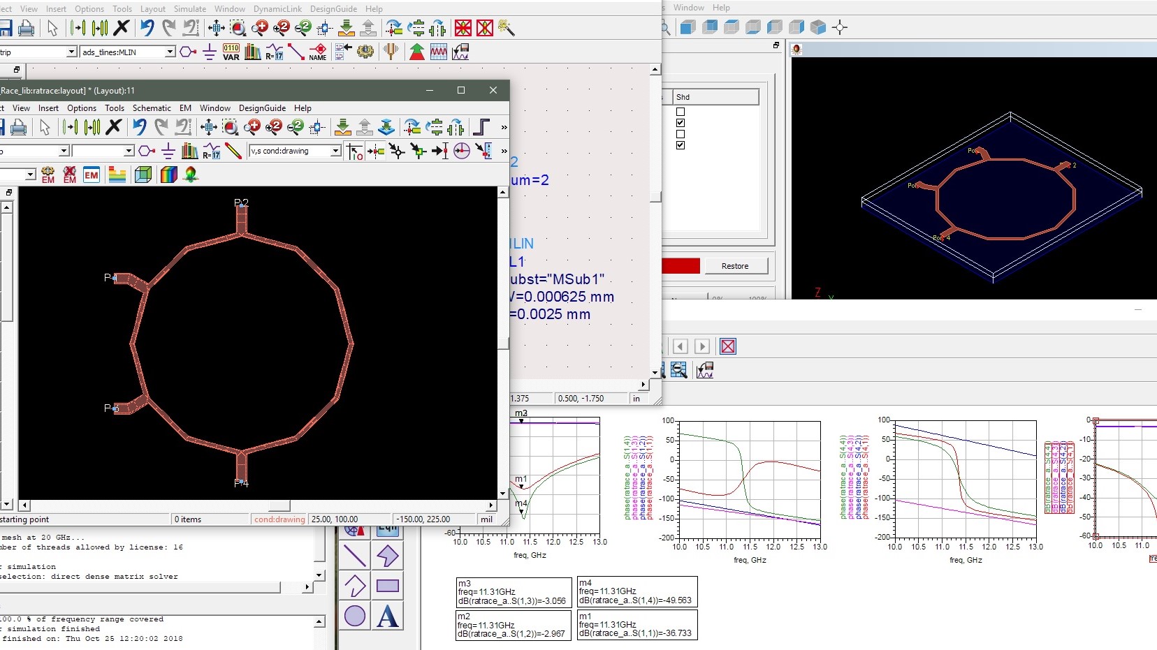
Simulation
- PathWave (Keysight)
- HFSS (Ansys)
- Microwave studio (CST)
- AWR Microwave Office (Cadence)
Hardware
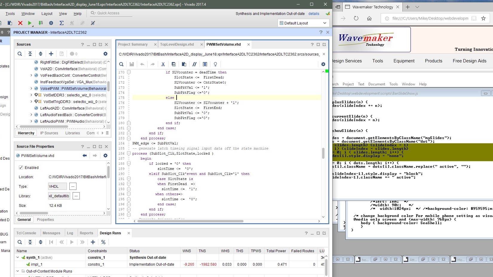
- FPGA RTL VHDL design software (Xilinx / Vivado)
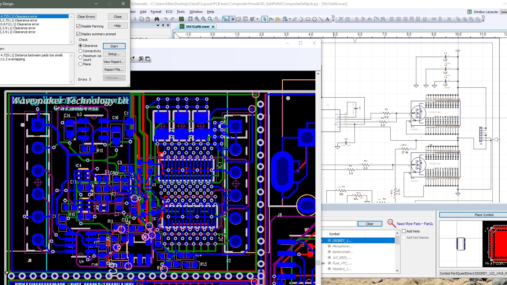
- PCB layout design software
P-mod Solutions
Quick Prototyping
- GaN FET Half bridge P-mod development PCB
- Two EPC2021 Gallium Nitride FETs with integral drivers in a half bridge configuration. Operatiing from a single 3V3 (pulse width modulated) logic input with a high side power supply. Suitable for prototyping audio class D amplifiers or power supply switchers and RTL VHDL source code for easy integration into a wide range of FPGA development PCBs.
- Audio A2D P-mod development PCB
- A Texas Instruments PCM1804 audio analog to digital converter integrated with a single ended to differential input buffer operational amplifier. The Pmod default setup is for 24 bit data audio quality with a four times over sampled audio signal for the left and right channels. All converter parameters are pre-selectable supporting other data rates. The interfacing configuration can be set to I2C or DSP mode. RTL VHDL source code available for easy integration into a wide range of FPGA development PCBs.
Reckoners & Calculators
- Attenuator Pad calculator, this table lists the E24 series resistor values required to make a "Tee" or "Pi" attenuator network. For each integer dB attenuator value in the range 1 to 20dB, the calculated loss is also provided
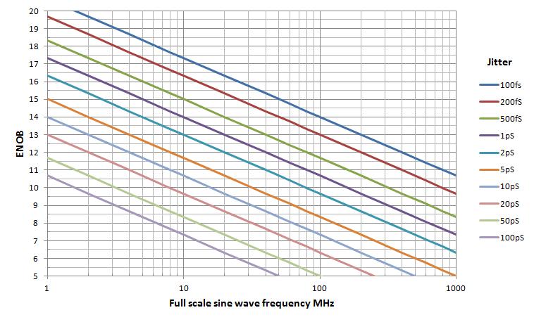
- The A2D converter phase noise jitter clock reckoner. A graph of the phase noise required for a given signal to noise ratio and frequency. The plot axies are signal to noise resolution (converter effective number of bits) against the full scale sine wave frequency.
- Calculator to convert dBm into watts, volts pk to pk and volts RMS
- Calculator to convert Return Loss into VSWR.
Attenuator Pi-Network Values
Attenuator Tee-Network Values
| Value | Pi Network | Calculated | |||||
|---|---|---|---|---|---|---|---|
| dB | R-Series | R-Shunt | Loss dB | ||||
| 1 | 5R6 | 820 | 1.02 | ||||
| 2 | 10 | 390 | 1.98 | ||||
| 3 | 15 | 270 | 2.90 | ||||
| 4 | 22 | 220 | 3.86 | ||||
| 5 | 27 | 150 | 5.17 | ||||
| 6 | 39 | 150 | 6.14 | ||||
| 7 | 39 | 120 | 6.85 | ||||
| 8 | 47 | 100 | 8.16 | ||||
| 9 | 56 | 100 | 8.81 | ||||
| 10 | 68 | 91 | 10.05 | ||||
| 11 | 75 | 82 | 11.01 | ||||
| 12 | 91 | 82 | 11.97 | ||||
| 13 | 100 | 75 | 12.96 | ||||
| 14 | 120 | 75 | 13.98 | ||||
| 15 | 130 | 68 | 15.04 | ||||
| 16 | 150 | 68 | 15.92 | ||||
| 17 | 180 | 68 | 17.09 | ||||
| 18 | 200 | 68 | 17.80 | ||||
| 19 | 220 | 62 | 19.07 | ||||
| 20 | 240 | 62 | 19.68 | ||||
| 30 | 750 | 51 | 29.94 | ||||
| Z0 = 50 Ohm | |||||||
Pi Network = I/P and R-Shunt to Gnd, I/P and R-Series to O/P, O/P and R-Shunt to Gnd.
Attenuator Tee-Network Values
| Value | Tee Network | Calculated | |||||
|---|---|---|---|---|---|---|---|
| dB | R-Series | R-Shunt | Loss dB | ||||
| 3 | 10 | 150 | 3.17 | ||||
| 4 | 11 | 100 | 4.02 | ||||
| 5 | 15 | 91 | 4.93 | ||||
| 6 | 16 | 62 | 6.12 | ||||
| 7 | 18 | 51 | 7.11 | ||||
| 8 | 22 | 47 | 8.11 | ||||
| 9 | 22 | 39 | 8.85 | ||||
| 10 | 24 | 33 | 9.94 | ||||
| 11 | 27 | 30 | 10.92 | ||||
| 12 | 27 | 24 | 12.06 | ||||
| 13 | 30 | 22 | 13.08 | ||||
| 14 | 36 | 22 | 14.12 | ||||
| 15 | 33 | 18 | 14.79 | ||||
| 16 | 36 | 16 | 16.05 | ||||
| 17 | 39 | 15 | 16.98 | ||||
| 18 | 36 | 12 | 17.93 | ||||
| 19 | 43 | 12 | 19.07 | ||||
| 20 | 39 | 10 | 19.74 | ||||
| Z0 = 50 Ohm | |||||||
Tee Network = I/P with R-Series to Star node, Star node with R-Series to O/P, Star node with R-Shunt to Gnd.
Converter jitter requierment for a given ENOB and frequency
RF Power to Voltage calculator
Enter the RF power P in dBm
dBm
| dBm | Power mW | Volts RMS | Volts Pk |
|---|---|---|---|
| |
|
|
|
| sinewave in a 50 Ohm system | |||
Voltage to RF Power calculator
Enter the peak to peak Voltage in Volts
Volts
| Volts Pk | Volts RMS | Power mW | dBm |
|---|---|---|---|
| |
|
|
|
| sinewave in a 50 Ohm system | |||
The equations
Return Loss to Voltage Standing Wave Ratio calculator
dB
:1
(Reflection Coeficient)
   Formular:
       VSWR = ( 1+|ρ| ) / ( 1-|ρ|)
       ρ = 10 ^ {Return Loss / 20}